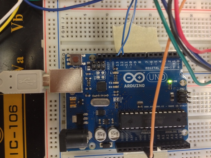
Today I was able to work with Gio to get the motor and vacuum tube working in conjunction which turned out quite nicely. Through trial and error Gio and I were able to deduce that it takes 2600 steps at a rotation rate of 1.8 degrees/step for the valve to be open enough to achieve a rate of 93 l/sec. One of the next immediate steps is to solidify the code, using either the Arduino alone or perhaps making the Arduino code the middle man and having python code store different profiles. I’ve already posted some things regarding GUI’s and what I’ve been doing with python. The link to the python-arduino interface and all of the dependencies is http://jdreyer.com/projects/Arduino/StepperMotor.php, and the link to the preliminary GUI file is http://www.mediafire.com/download.php?6bwgvqklwggb3ot . Once again as I mentioned in my previous post the .INO file found on the jdreyer website has a typo, the direction pin should be set to 13 as that is the one that is used. Also, today Tyler showed me the part of the code that controls the speed of the motor, it’s basically just the delay given before writing to the BED (Big Easy Driver). It seems that the fastest it can go is with a minimum delay of 100 microseconds, any lower and it stutters a lot.
ALP 14
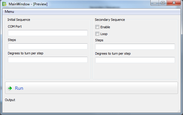
I went in to the lab today and saw Gio and Tyler (at different times). The lab power source is coming along nicely thanks to Tyler. I was able to play around with the stepper motor and the Pyduino (my own made-up term for Python-Arduino) set-up. It seems there was a bit of an error in the code posted earlier, specifically in the code that is loaded into the arduino board. Near the top there is a variable instantiated “int DirectionPin=3;”, this value should be 13 as this is the pin that is hooked up to the direction pin. I was having trouble making the motor turn in different directions, but with this small fix everything worked as it should. I also noticed that I could get multiple revolutions (enough I think, I’ve yet to test this out), to open and close the valve. If not one could simple keep it turning in the same direction by saying something like “Stepper.SetPosition(1,1,65534)” and once that is done “Stepper.SetPosition(1,1,0).” I believe this would turn it clock-wise, and to get the stepper motor to turn in the opposite direction one would change “65534” to “-65534.” I don’t think disecting the code will be a feasible endeavor, at least if this is to be done within a reasonable amount of time as the “serialArduino” import (taken from the website and imported into the python directory) contains many .py files which are the backbone of how python communicates with the Arduino code/board. There’s still the issue of how fast we can get this to turn, so if I find a way to change that I’ll post an update. As it is, the speed is decent but I do feel like the motor should be able to go faster. Maybe this will improve with the new power source. Anyways, below is a simple GUI concept that I came up with in QtDesigner. There isn’t any code associated with it yet. I’ll get around to posting a guide as to how I made this QtDesigner and later on how to code for it.
ALP 13
Today I was able to play around with the Arduino and stepper motor on my own after Andy left for the day. I wanted to see if I could get the sample code that was posted at http://jdreyer.com/projects/Arduino/StepperMotor.php to work. Setting up the environment is simple and requires that you copy some files (which you can readily download) into a couple of python directories. On Ubuntu it seemed that the directory of interest was not the “site-packages” but “dist-packages”, although I can’t say for certain since I just copied the files to both out of laziness to make sure that it would work either way. One can then load the sample arduino code into the arduino board and proceed to control the motor from the python command module. Ultimately, I’m not sure that the code that is provided will be of use to us, so I wanted to see how I could modify it. I’m still looking at the code and I need to play around with it more to understand how exactly he’s communicating with the Arduino board. It’s a bit different from what’s being done right now since he uses pins 13 and 12, instead of 8 and 9. Below are some the commands I used to control the motor.
>>> Stepper=InstrumentControl.StepperMotor(‘/dev/ttyACM1’)StepperMotor: Serial Communication Open>>> Stepper.SetPosition(1,1,2000)2000>>> Stepper.SetPosition(1,1,1000)1000>>> Stepper.SetPosition(1,1,800)800>>> Stepper.SetPosition(1,1,3000)3000>>> Stepper.SetPosition(1,1,3000)3000>>> Stepper.SetPosition(1,1,800)800>>> Stepper.SetPosition(1,1,3000)3000>>> Stepper.SetPosition(1,1,800)800>>> Stepper.SetPosition(1,1,1000)1000>>> Stepper.SetPosition(1,1,2000)2000>>> Stepper.SetPosition(1,1,387)387
I also took a video documenting the movements the motor made when I was messing around which relates to the sample output I posted above.
In any case, I’ll make this a side project of mine. If it doesn’t pan out then I’m sure what Gio and Khurram have come up with will work just fine. I just figured it’d be nice to have multiple program profiles accessible through a simple to use GUI.
ALP 12
I haven’t updated but I was in the lab on Monday and Today (Friday) helping Gio and Tyler with what I could. On Monday I helped Gio with some basic soldering related things and he was able to get the Big Easy Driver set up in a circuit with the Arduino board. I also went in the afternoon and tried to troubleshoot the motor with Tyler to no avail, we started to look into converting the ATX power supply into a lab power supply, but since it was getting late and Tyler needed to go we decided to leave it for the next time we were in lab. Today was a littler more eventful as Gio and Khurram were able to get the motor to function quite well, they even took a video of the motor turning the valve. It seems they can get it to turn at good speeds, so once we have the new power supply set up we will be set it seems. Tyler and I continued our work, but found out the power supply we had been working was non-functioning so Tyler took another power supply from a different tower and got it prepped for conversion. He felt a little unsure as to how to wire the switch he had bought and since he was limited on time I suggested calling it a day and finishing up the work on Monday since all that really was left to be done was the soldering and cosmetic portion of the project (i.e. making everything look nice). I was able to get a rudimentary box set up around the fuse box for the vacuum pump, but I’ll have to find a more permanent and reliable solution. Right now it’s held in place by some tape, but I’d like to get it caged in with some spare pieces of aluminum I have from my computer tower. Similar to the pieces I used on the legs of the PVC tube’s stand. As a side note, I did manage to rip apart the ground from the connection it was soldered to, so I had to re-solder this connection. It looked like it would hold, but the cables just barely reach so one has to be careful when handling it so as to avoid pull anything off.
ALP 11
I went into the lab today to see what could be done with the tube and vacuum set up in order to improve it. It seems we will have to increase the volume in which we are pulling a vacuum in order to increase the time that we can sustain a constant pull of 91 liters/second. I’m not entirely convinced this will also fix the rate of flow that we are currently getting, since it seems that either way the limiting factor of the flow rate would be the opening. We start with the simple knowledge that volumetric flow rate is simply the change in volume per some unit of time. From here I don’t really see how increasing volume would solve any flow rate problems we are having, that is even though the volume increases, so does the time it takes for air to fill this volume. Thus, the two changes cancel each other out to sustain the previous flow rate, albeit there is merit in increasing the volume in order to sustain the flow rate as I had mentioned. There is also the issue of pressure differentials which might be relevant, were it not for the fact that we don’t really have a way of affecting atmospheric pressure to cause air to flow into the vacuum space faster. There is also the option of increasing the vacuum which we pull, so if we can get the other pump working (assuming it works) then this could also be a solution. Otherwise the only reasonable conclusion that I seem to arrive at is that, given Q=dV/dt, increasing the inlet size does have an effect since we are allowing a greater volume of air to enter the vacuum with time being kept constant. I’m probably oversimplifying the problem, but I still think that volume per se isn’t the limiting factor in terms of the flow rate; that is the cross-sectional area of the tubes we were using was very small. I could be wrong but until now I haven’t been able to convince myself otherwise.
Edit: I see Andy wrote a much more detailed post, concerning the situation. It seems my oversimplifications were at least on the right track. So now there’s the issue of improving the vacuum situation.
Progress regarding vacuum tube and related things
I went in to the lab on Monday; Gio was able to help me with fixing the leaks in the vacuum tube. After doing so we were able to get one of the valves connected to the tube to see if it worked properly. We were able to verify that it was working and in the process realized that it was shut off by twisting the top so it pushed further in (which was counter intuitive to what one would assume at first glance). At Andy’s suggestion and with his help I was able to get some readings on the air flow going into the tube when the valve was opened. The flow peaked in the mid 40’s range, which unfortunately was only about half the rate we want to achieve. Since the cross-sectional area of the tube leading the air into the device was greater than that of the other tubing we used, this could have reduced the numbers we would have gotten had everything been kept constant. There’s also the issue of messy connections without any sort of Teflon or sealant applied, so that can also be a factor. In any case at this point I still have to figure out better ways of getting the valves and the tubes connected so as to optimize the flow of air into the tube (i.e. in order to get a “true” reading). At some point I’d also like to begin to play around with the opening and closing of the valves via the arduino-motor complex to see how these will be set up with the tube and vacuum to get an overall design that’s relatively reliable and reproducible in case we need to set it up and take it apart constantly, since we aren’t the only ones in the lab using some of the parts. Andy took some videos and I uploaded them to my YouTube account, they are posted below.
ALP 10
Found some interesting info on controlling the stepper motor via Python. I’ve yet to look at this seriously, but it seems like it uses the motor shield in a similar set up to what is being used now.
Source: http://danthompsonsblog.blogspot.com/2009/04/python-arduino-motor-shield-stepper.html
P.S.
There was also some info on how to do it with a motor driver, but since it seems that won’t be the approach we take to control the motor I suppose it’s not really relevant. In any case, for future reference, the info is found here http://jdreyer.com/projects/Arduino/StepperMotor.php
ALP 9
Today, Danielle and I were able to finally pull a vacuum inside the PVC pipe. There were some problems in keeping the ends air tight, even with the thread sealant applied. According to Danielle fusing the caps to the PVC pipe could solve our problem, but then we wouldn’t be able to take them off. I’m not sure if this is an issue or not. If issues (debris, stress cracks, etc.) should develop inside the pipe it would be near impossible to check them if we went ahead with this method. I’m still debating on what to do. Danielle also mentioned that some forums suggested using Teflon tape as an alternative to permanently fusing caps on. This seems to be the preferred method for plumbing, but I’m not sure this would hold up in the end when being used in a vacuum scenario. I don’t think the addition of Teflon tape AND the thread sealant would do a much better job than the thread sealant alone. I suppose we could apply some more sealant to the threading and try and tighten the caps more than we already have. I was also thinking about wrapping some Parafilm around the outside edge (not around the threads but after the cap is screwed on) to see if that could stop air from leaking inside.
ALP 8
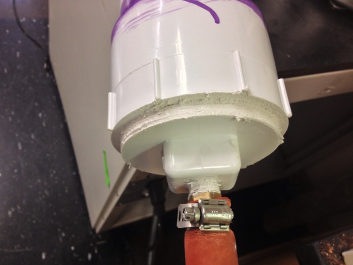
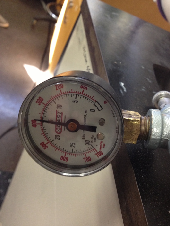
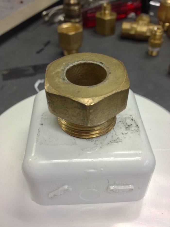
I was able to attach the PVC cap with the 3/4 in. threads to one of the valves, but there wasn’t anything that would fit the cap with the 1 in. threads and allow it to attach to the other valve. I’ll post some pictures below for reference. I’m also assuming that the other opening on the valves will be used to attach to the pump itself, so I was wondering if a connection for this also needed to be resolved or if this had been settled already. There’s also the question of which pump we will be using, since we decided on not using the one in the back room due to not knowing what was going on with the wiring.

ALP 7
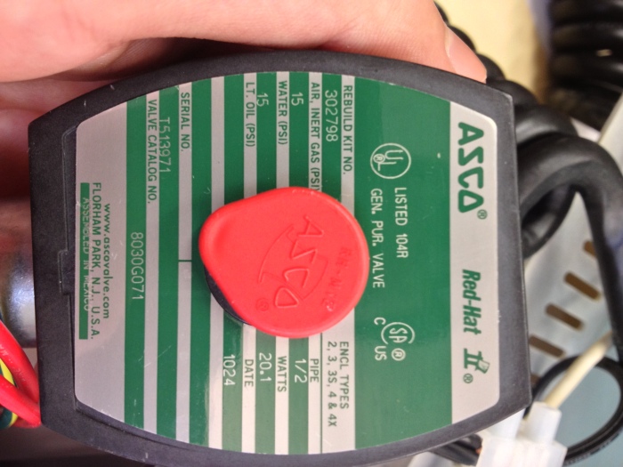
With regards to the valves and their specifications, I found out that the larger of the two (has a black frame, serial #T513971, catalog #8030G071) is the valve that is normally open. The smaller of the two (green all around, serial #T502470, catalog #8030G016) is normally closed. Once we have the thread sealent, or something that will serve the same purpose we can assemble the ends of the PVC pipe. I still need to figure out a way to get the end with the larger hole to attach the to cap. I had found a part that would fit it, but the opposite end had no threading so as to allow something to be attached to it.

Product pages (via re-seller website):
